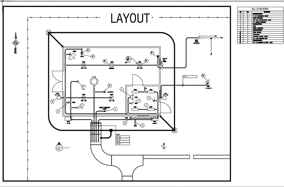
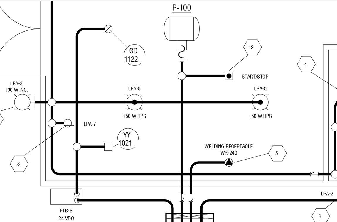
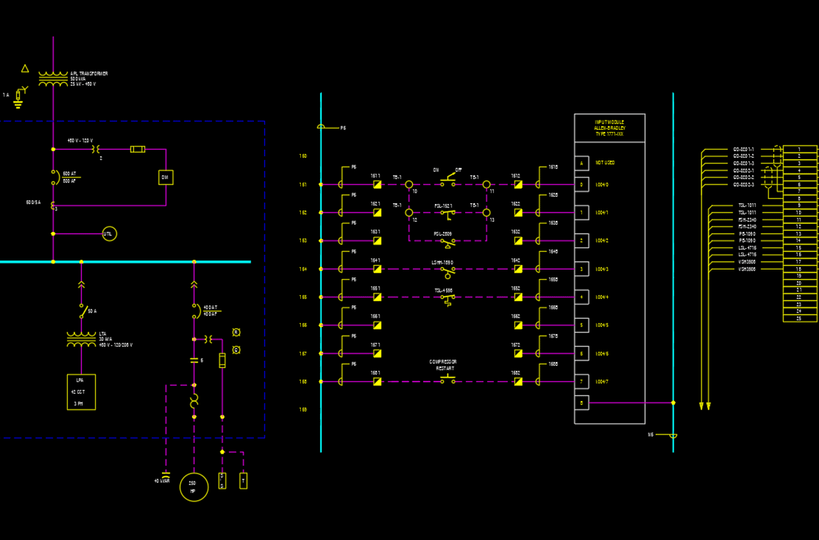
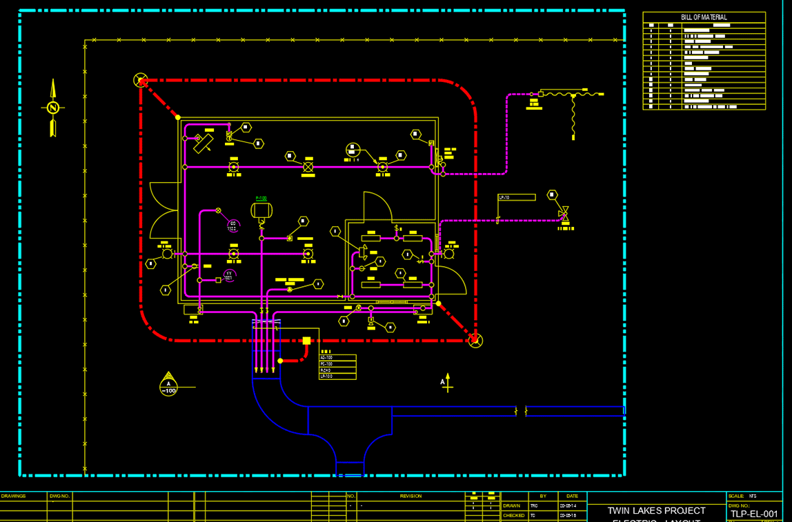
Piping drafting software
PROCAD offers applications for P&ID drafting, ISOMETRIC drawings, and piping plan drawings. We offer software solutions for process piping projects of any size.
Take a look at our drafting applications to suit your needs.
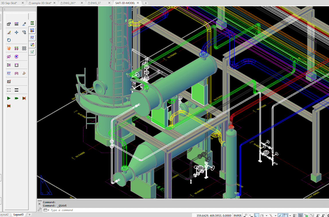
Each piping application comes with essential automation and data management tools. Features include the ability to Auto-Route piping components as well as auto-generate Bill of Materials (BOMs). Other features include easy-to-use pre-built components, like flanges, nozzles, elbows, gaskets, valves and supports to make drafting easier.
Complete set of tools for all your drafting needs
Every software product come with the tools you need to manage your design office. The included modules are to facilitate the creation of pipe specs, design BOM templates and to organize your projects to suit customer standards.
Large variety of piping components
Vast selection of pipe fittings, flanges, valves and supports to make your job easier. Piping components come in flanged, threaded, socket weld and butt-weld configurations.
Spec-driven
Always use compatible pipe specs with background compliance-checking.
Project-driven
Save and control important settings for each project (or each client), which includes drawing units, location of drawing files storage, allowed pipe specs, border drawings, BOMs and many other important settings.
Spec override options
Easily override the operational spec if necessary. Piping application will allow you to proceed with the override after alerting you of the pending deviation from standard practices.
Automation
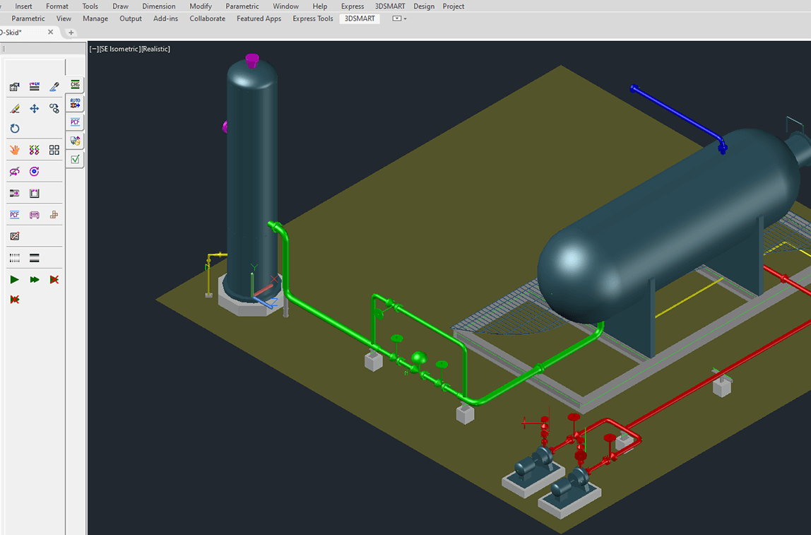
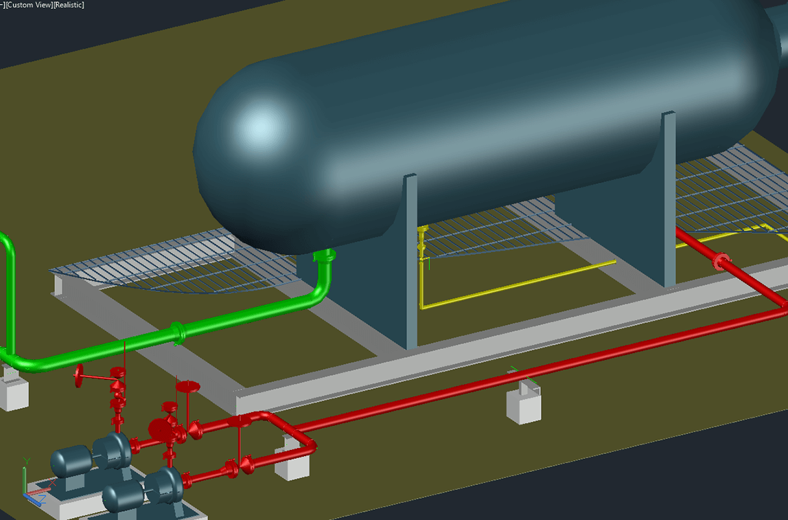
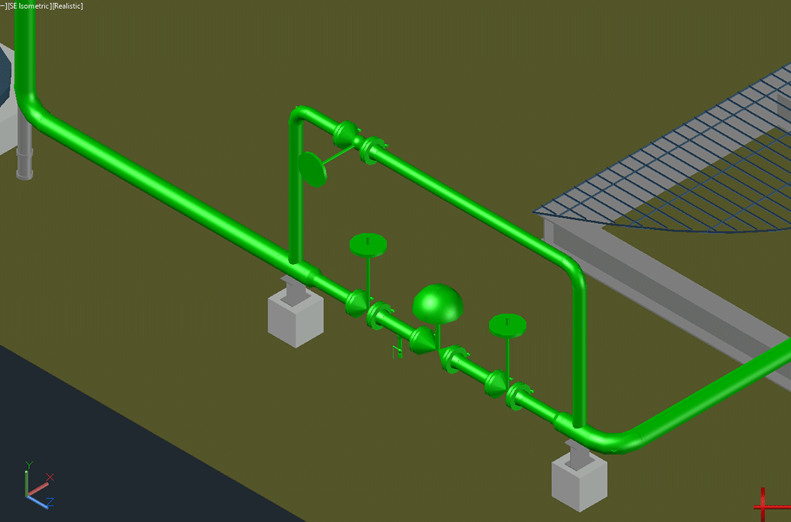
Draw vessels by simply selecting two corners, sequentially place piping components with AutoRoute, annotate valves and generate BOMs. All made easy by the program’s intelligent background checking.
BOM generation
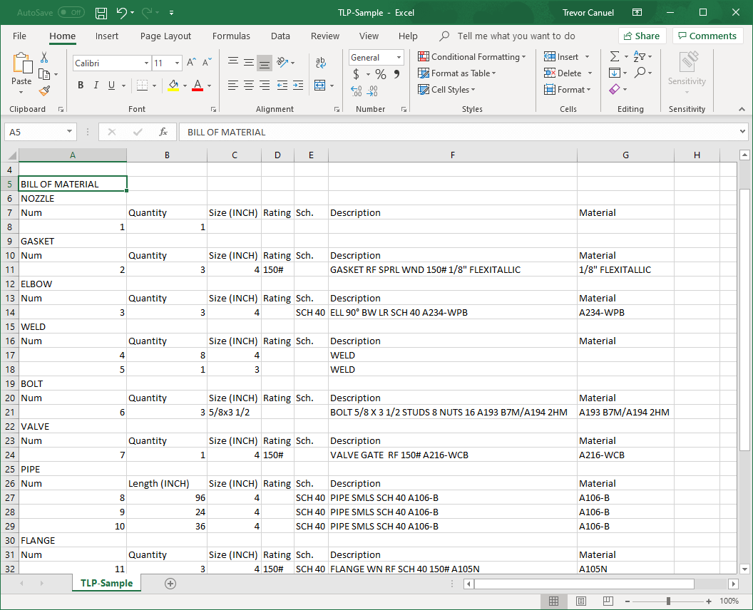
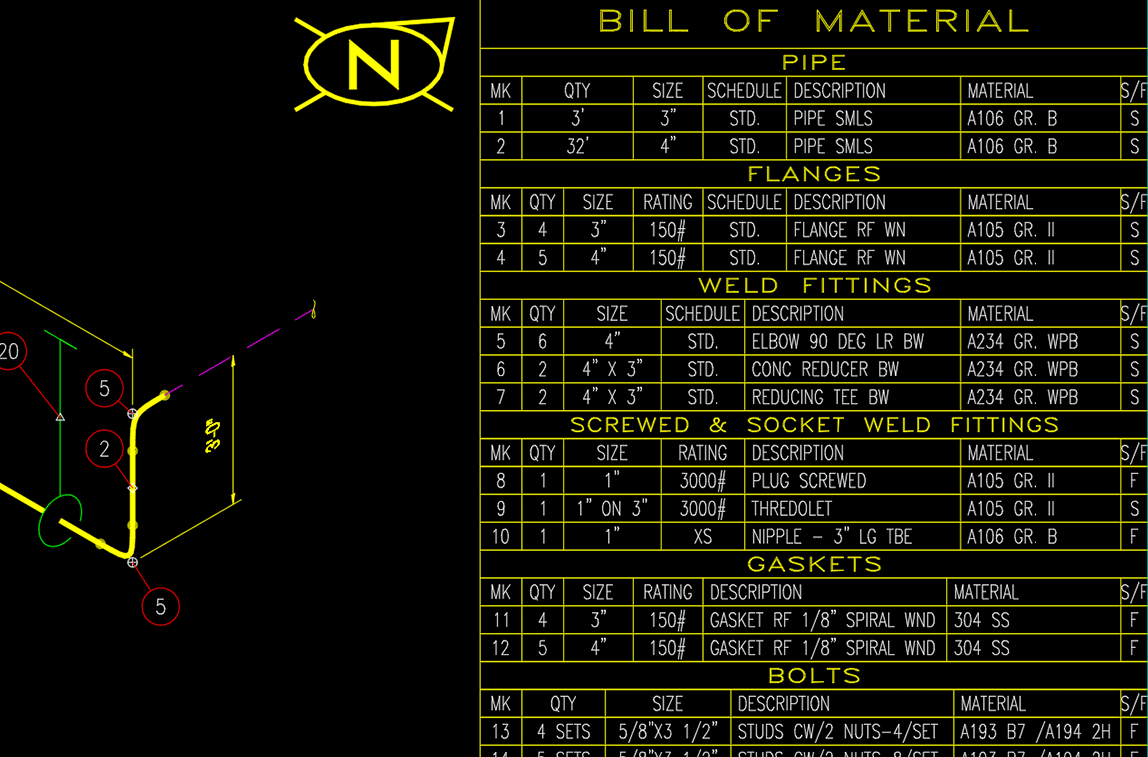
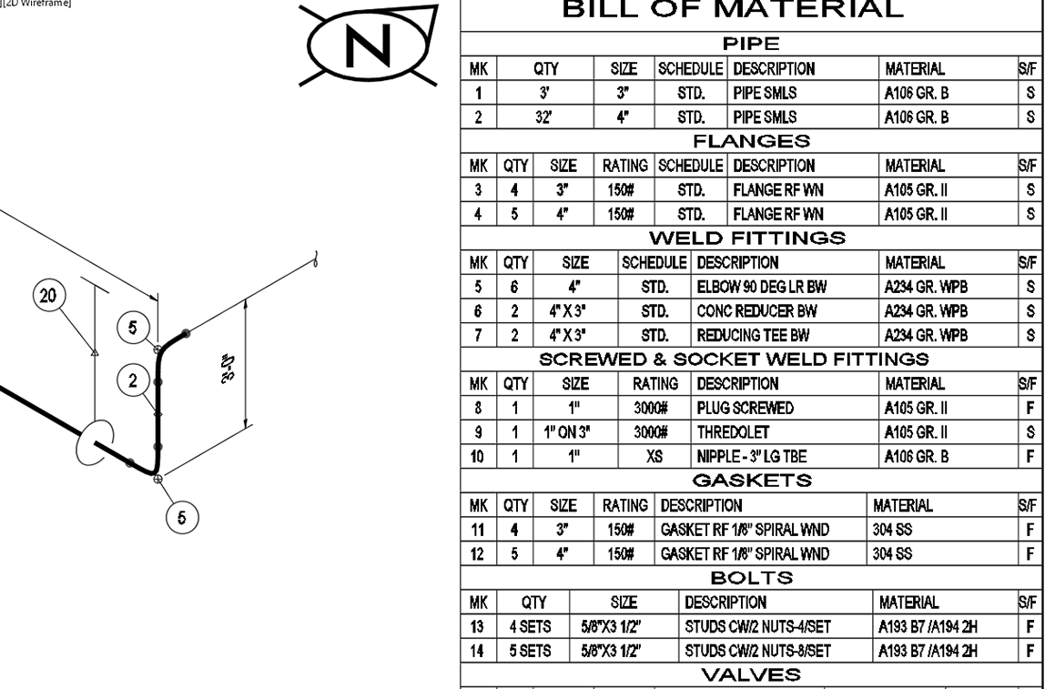
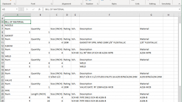
Generate Bill of Materials (BOMs) for your piping components for a single drawing, a specific line number, or for the complete project. BOM files can be created in multiple formats: inserted into a drawing (DWG format), web format (HTML), Comma Separated Values format (CSV) and in text (TXT) format.
Material destination control
Specify where fittings are to be shipped – to the field or any number of fabrication shops.
Support for a variety of sizes and schedules
- Pipe sizes from 1/8” to 80” or Metric 3mm to 2,000mm
- ANSI/ASME flanges and valves from 150 to 2,500 lbs
- Threaded and socket weld fittings from 2,000 to 9,000 lbs
Efficient design
Improve plant design efficiency and reduce costly errors with a fully customizable and intelligent rules-based software.
- Project settings restrict usage to approved piping specs
- Automatic background compliance checks alert users when straying from established piping design parameters
- Standard libraries are thoroughly checked to ensure accurate component data for piping and structural steel
- BOM Settings Manager – create BOMs in multiple formats: drawing (DWG), Comma Separated Values (CSV), web (HTML), and text (TXT) format
- Generate material reports for the entire project, a single or a group of 2D drawing or report by line number(s)
- Spec Generator – edit piping specifications and component data files
- Standards Manager – set project parameters to conform to company/client standards
Collaborate
The scalable multi-user working environment allows projects of all sizes—from single users to large global teams—and ensures uniformity across disciplines.
- Any number of engineers and designers can work concurrently on a project
- Achieve consistent and uniform project drawings by using the same standards and specs
- Customize project settings
- Copy existing project settings and drawings for re-use in new projects
- Designate storage location for project drawing
- Restrict use of project piping specs to approved project specs
- Share drawings with clients or suppliers in the standard DWG format
- Standards and specs are portable with the Export/Import feature to sync data between users
- Global BOMs can be shared with procurement in CSV file format
Manage materials
Accurate material reporting ensures materials are ordered on time and correctly charged to each customer’s project. Generate material reports for the entire project, a single or a group of drawings, or report by line number(s). Create material reports in any of the following formats:
- Comma Separated Values format (CSV)
- Web format (HTML)
- External text format (TXT)
Piping & Instrumentation Diagrams
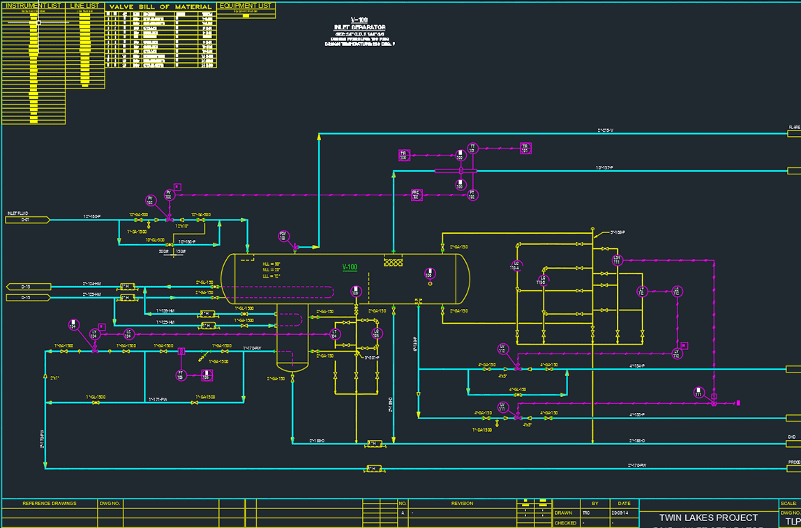
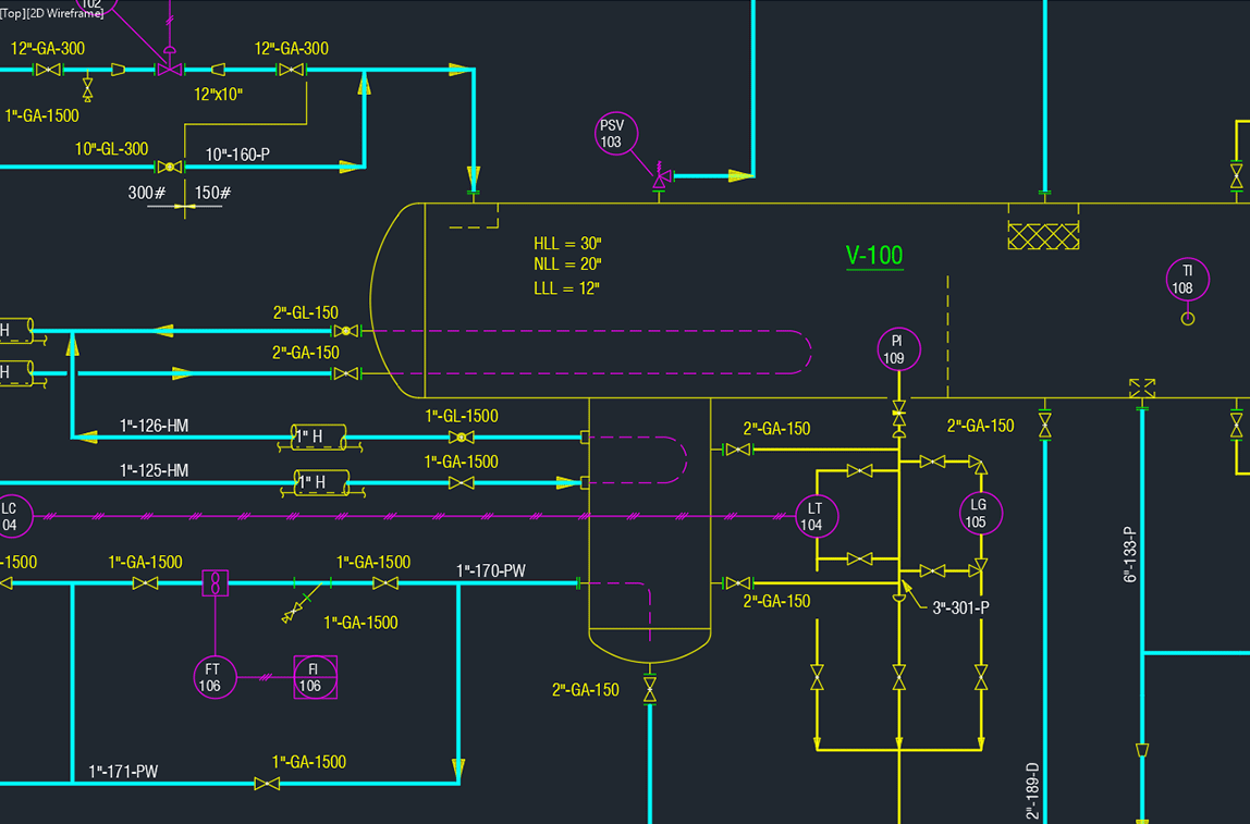
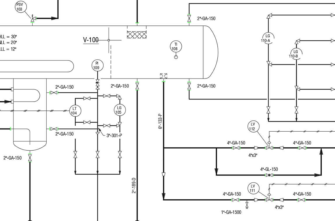
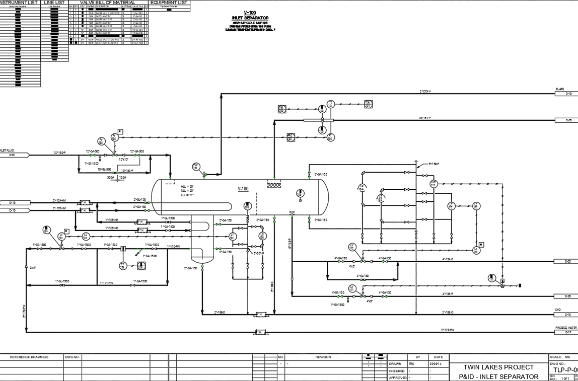
P&ID is an intelligent 2D drafting software designed to simplify the drafting and design process when creating and managing Piping & Instrumentation Diagrams (P&ID) and Process Flow Diagrams (PFD)
We designed P&ID with ease-of-use, functionality, and team-wide data integration in mind. P&ID is essential software for anyone who likes to work smart and not hard. With intelligent features, like valve BOM generation and automation tools, P&ID helps reduce your design and documentation time.
P&ID also comes with many features that will improve the accuracy of your project data. For example, you can create global lists for project instruments and equipment, as well as make global edits to valve and instrumentation data, which prevents costly mistakes.
You’ll absolutely love all the intelligent automation features that P&ID offers.
- Symbol Libraries
Extensive industry-standard symbols and customized symbols for valves, instruments, instrument lines, instrument balloons and instrument equipment. - Line Types and Piping Specs
Define line types for primary (process) and secondary (utility) lines to be distinguished by color and/or line thickness. Piping specs support pipe sizes from 1/8” to 80” (3mm to 2000mm). - Automation
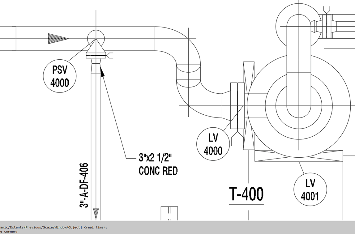
Draw vessels, exchangers, tanks, flare stacks, pumps, compressors, exchangers, re-boilers and more. Intelligently breaks long instrument balloon edges to ensure your instrument numbers do not bleed into the instrument blocks for clarity. - Valve BOMs
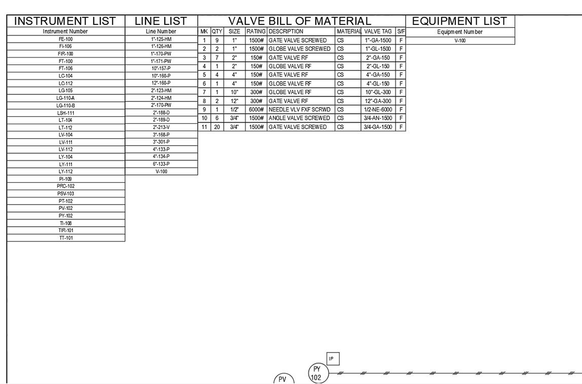
You can easily generate valve BOMs for a single drawing, a specific line number, or for the complete project. Get a head-start on ordering valves, especially the ones with long delivery schedules. - Instrument, Equipment and Line List
Create global lists for project instruments, equipment, or line numbers. You can insert lists in the drawing or export them in multiple file formats. - Global Changes
Make global changes to valve and instrument attribute data to reduce edit time and ensure data accuracy.
Isometric drafting software
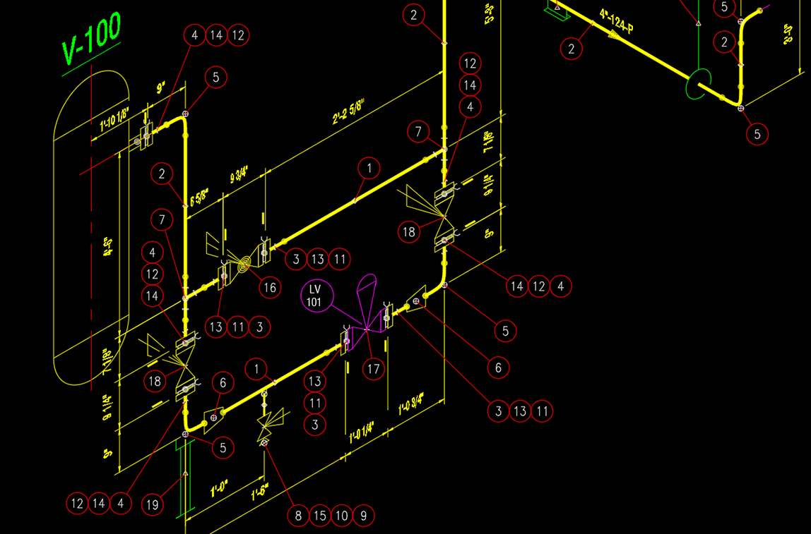
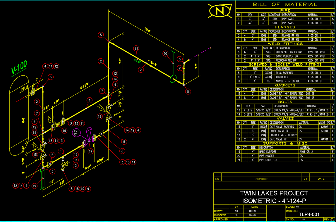
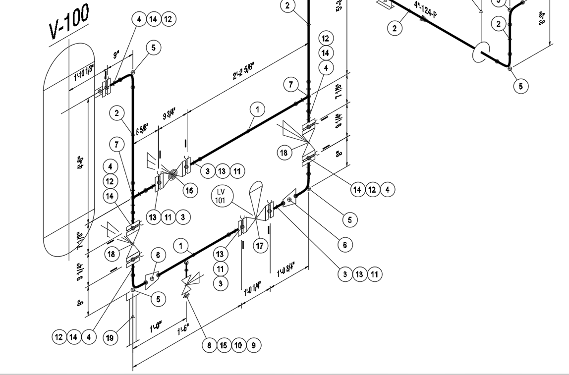
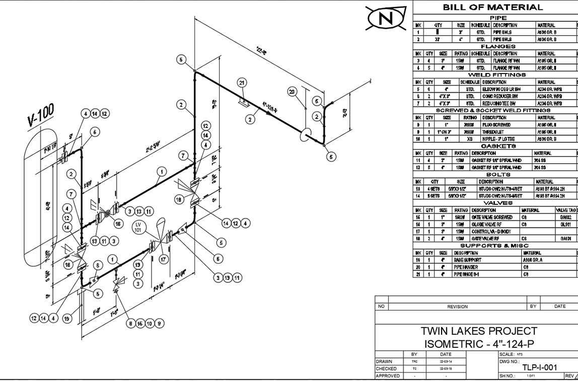
ISOMETRIC is an intelligent, spec-driven piping isometric drawing application. ISOMETRIC comes with an abundance of automation features for easier, more efficient drafting, as well as background compliance checking to ensure your project data is always accurate.
With ISOMETRIC, you can quickly build piping isometrics with easy-to-use pre-built components, including flanges, nozzles, elbows, gaskets, supports, valves—everything you need when drafting piping isometrics. ISOMETRIC also comes with an auto-route feature, which automates component placement and eliminates routine tasks.
ISOMETRIC, like all PROCAD products, includes the ability to auto-generate a Bill of Material (BOM) when you’re finished drafting, saving you time and protecting you against costly mistakes from human error.
- Variety of Piping Components
Vast selection of pipe fittings, flanges, valves and supports to make your job easier. Piping components come in flanged, threaded, socket weld and butt-weld configurations. - Spec-Driven
Spec driven with background compliance checking to ensure your input is accurate. - Override Options
Easily override the operational spec if you need to. Isometrics will allow you to proceed with the override after alerting you of the pending deviation from standard practices. - Automation
Draw vessels by simply selecting two corners, sequentially place piping components with AutoRoute, annotate valves and generate BOMs. All made easy by the program’s intelligent background checking. - BOM Generator
Generate Bill of Materials (BOMs) for your piping components for a single drawing, a specific line number, or for the complete project. BOM files can be created in multiple formats: inserted into a drawing (DWG format), web format (HTML), Excel format (CSV, or XLSX) and in text files. - Destination Control
Specify where fittings are to be shipped – to the field or any number of fabrication shops. - Supports Variety of Sizes and Weights
- Supports pipe sizes from 1/8” to 80” (3mm to 2000mm).
- Supports ANSI flanges and valves from 150 to 2500 lb.
- Supports threaded and socket weld fittings from 2000 to 9000 lb.
2D piping plans and elevations
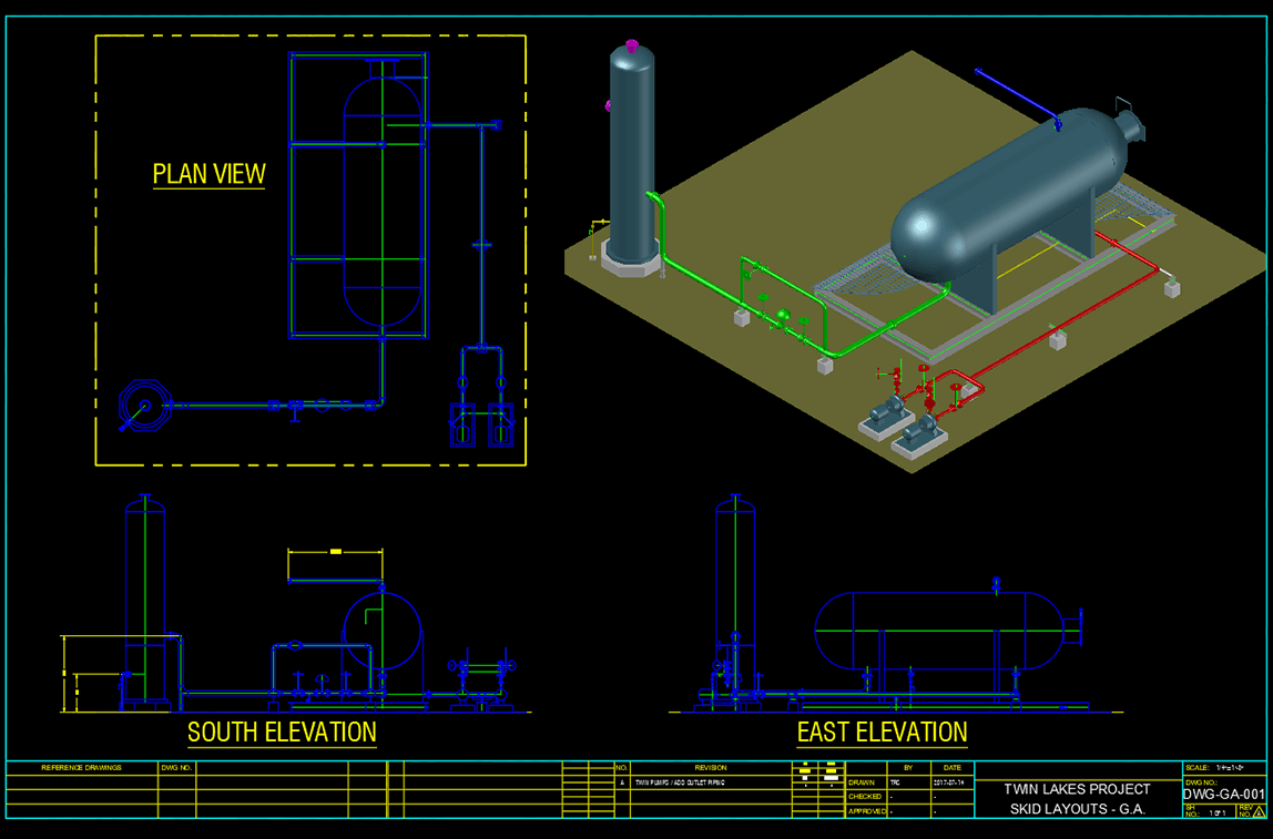
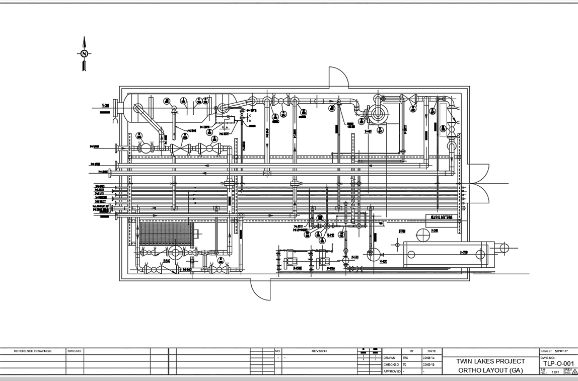
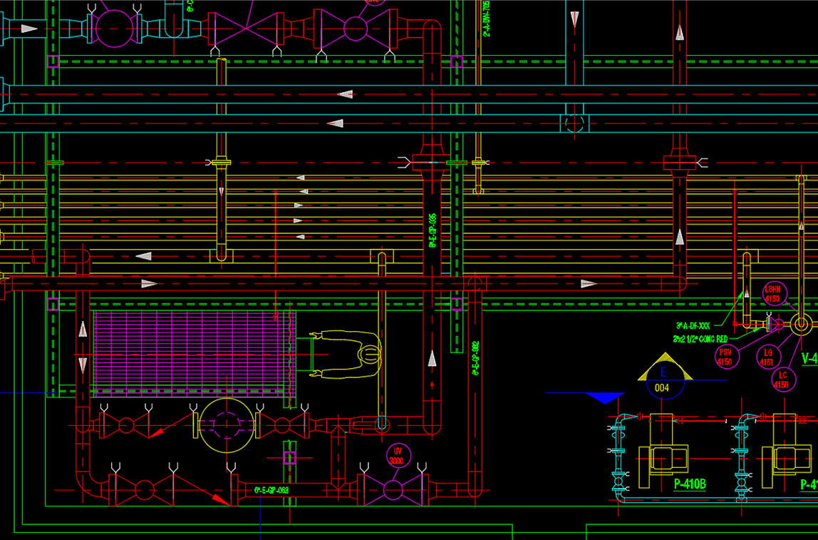
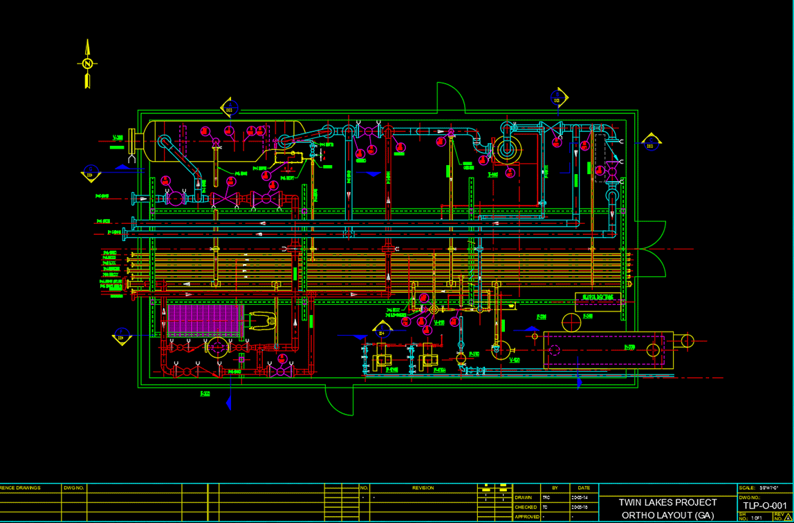
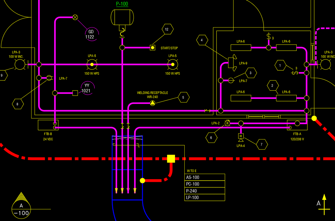
ORTHO has made creating 2D piping, structural and civil drawings easier than ever before. ORTHO provides users with an abundance of valuable automation tools to increase drafting efficiency, such as, an auto-route feature for piping layouts, as well as automating vessel creation by a designer inputting dimensions and letting ORTHO do the work.
When drafting with ORTHO, you’ll also have access to an extensive variety of components: including valves, nozzles, flanges, pipe fittings and steel structural items, which saves you valuable drafting time.
Like all PROCAD products, ORTHO automatically generates a Bill of Materials (BOMs) to make your job easier and ensures accurate data.
- Spec-Driven
Spec driven with background compliance checking to ensure your input is accurate. - Override Options
Override piping specs if you need to. Alerts from the software inform you of the pending override and requires your confirmation to proceed. - Automation
Increase drafting speed when placing vessels by providing its dimension and let the program do the rest for you. Draw structural components such as ladders, stairs and building outlines by entering their data. Save time with the auto-route feature in piping layouts. - Generate Piping BOMs
Generate Bill of Materials (BOMs) for your piping components for a single drawing, a specific line number or for the complete project. BOM files can be created in multiple formats: inserted into a drawing (DWG format), web format (HTML), Comma Separated Values format (CSV) and in text (TXT) format. - Extensive Piping & Structural Steel Components
Get a comprehensive selection of pipe components, structural steel members and civil drafting routines to produce perfect plans and elevations. - Variety of Pipe and Structural Steel Types
- Supports pipe sizes from 1/8” to 80” (3mm to 2000mm).
- Supports ANSI flanges and valves from 150 to 2500 lb.
- Supports threaded and socket weld fittings from 2000 to 9000 lb.
- Supported structural steel shapes include wide flange, standard beam, angle, tee, channel and HSS
Included 2D piping software modules
Standards Manager
Control project settings to ensure consistency from start to finish.
- Define project units: English, Metric or mixed English/Metric
- Define allowable pipe specs
- Set scaling factors for symbols, layering and colors
- Choose border drawings to be placed in drawings
- Set dimensioning variables
View tutorials for included modules
Spec Generator
Create your own pipe specs from PROCAD’s vast database of components in a variety of ratings and materials.
- Database includes pipe ratings from 150 to 2,500 lb and pipe sizes ranging from 1/8” to 80” (3mm to 2,000mm)
- Included generic carbon steel and stainless-steel ANSI pipe specs for 150, 300, 600 and 900 lb ratings
- Generate new pipe specs
- Organize and edit existing specs
- Add new material and other options to the source database
View tutorials for included modules
BOM Settings Manager
Customize material reports by creating multiple report templates to extract material information to accommodate your project’s schedule, material availability and delivery timetables.
- Decide on the components to be included in report
- Set sorting sequence
- Define BOM item numbering format
- Decide on the appearance of the report by choosing font type, size, grouping headers, etc.
- Define CAD options when BOM is to be placed in a drawing
- Ability to preview reports in case adjustments are necessary


