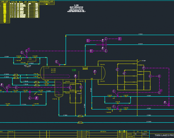
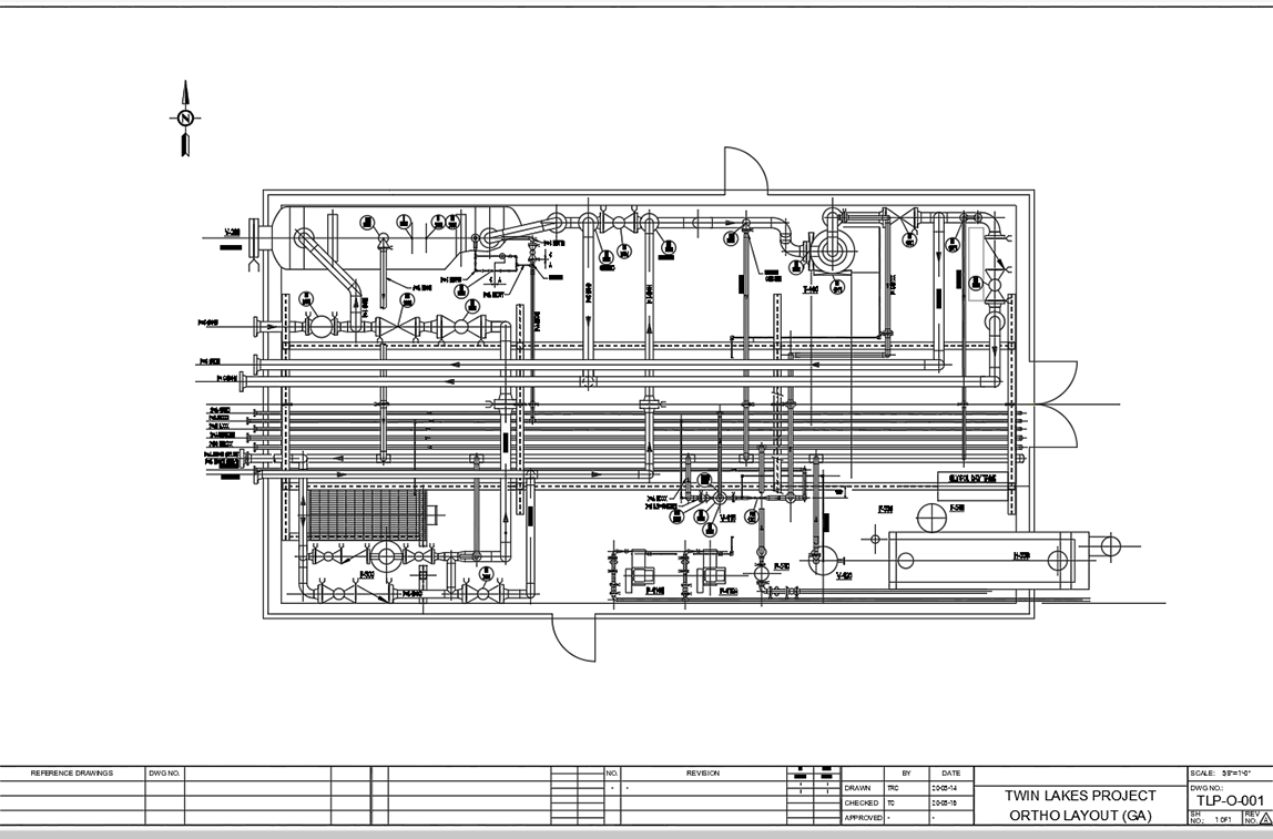
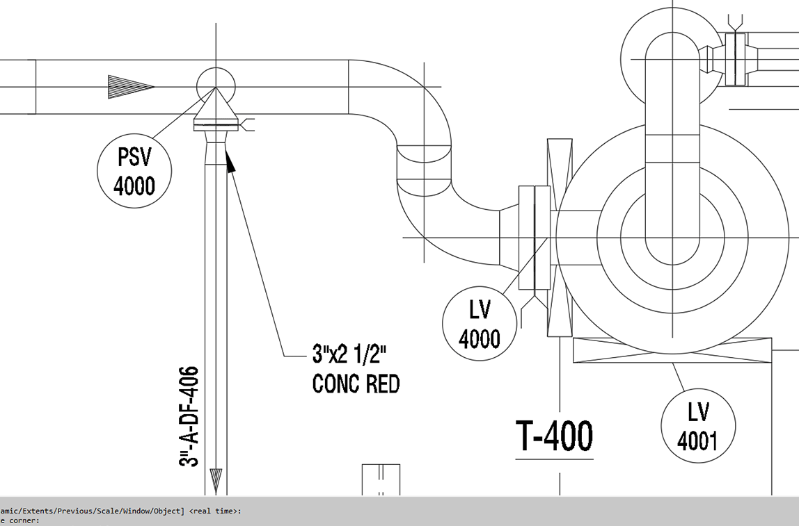
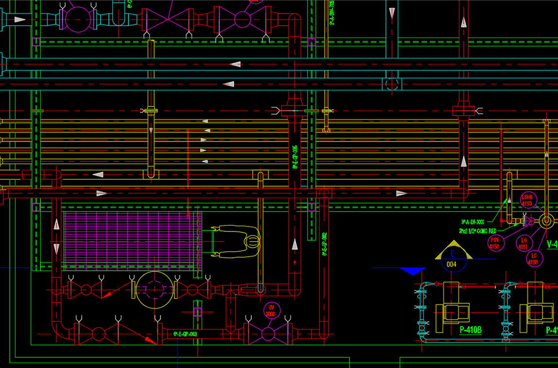
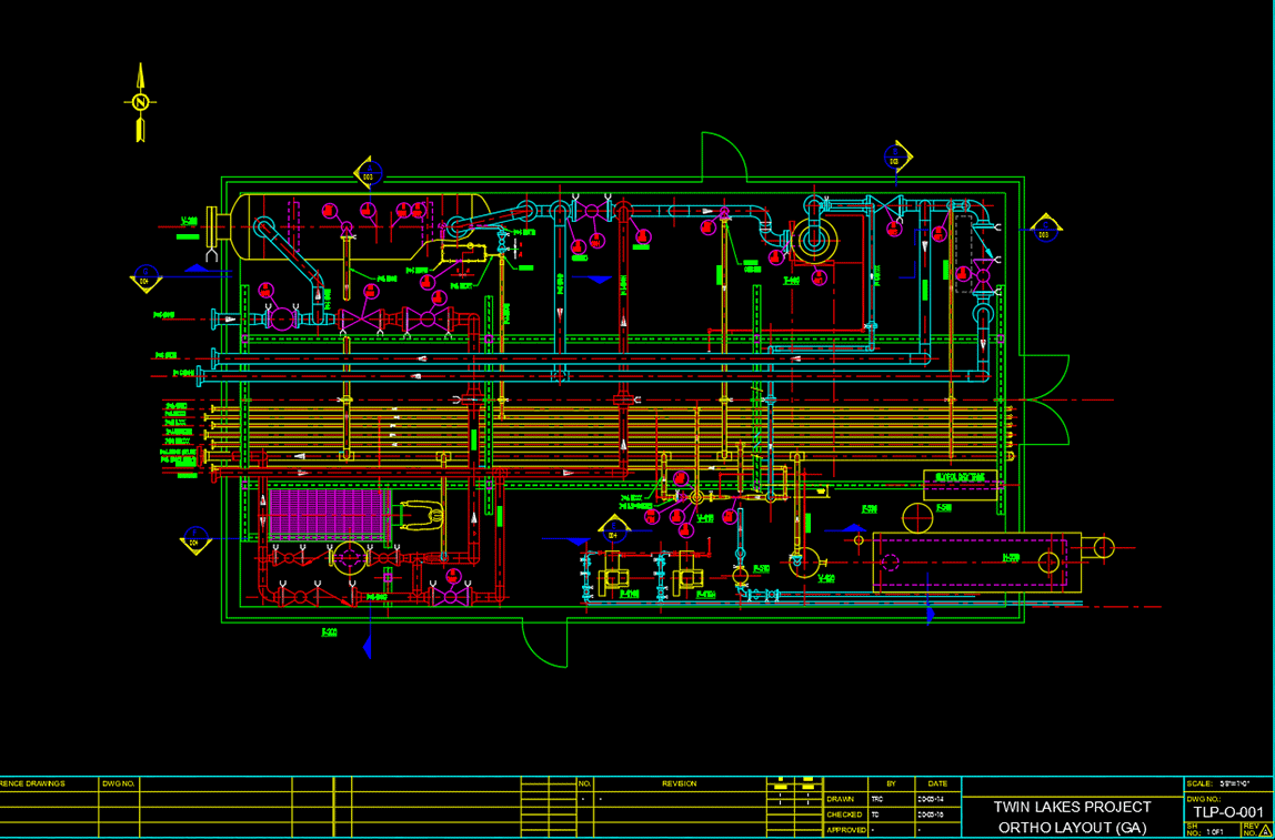
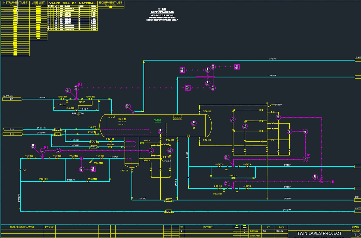
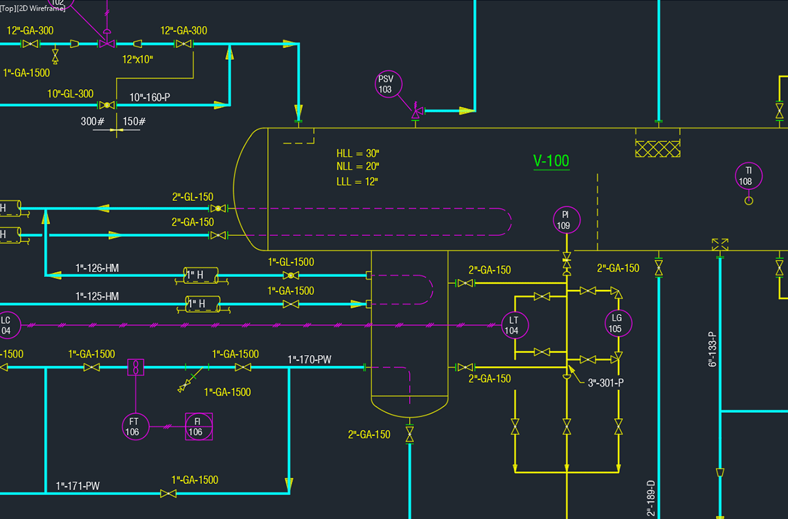
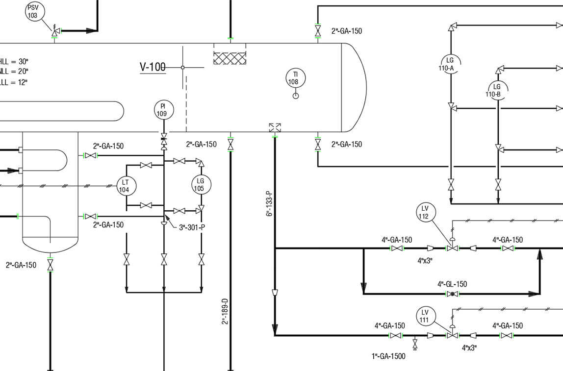
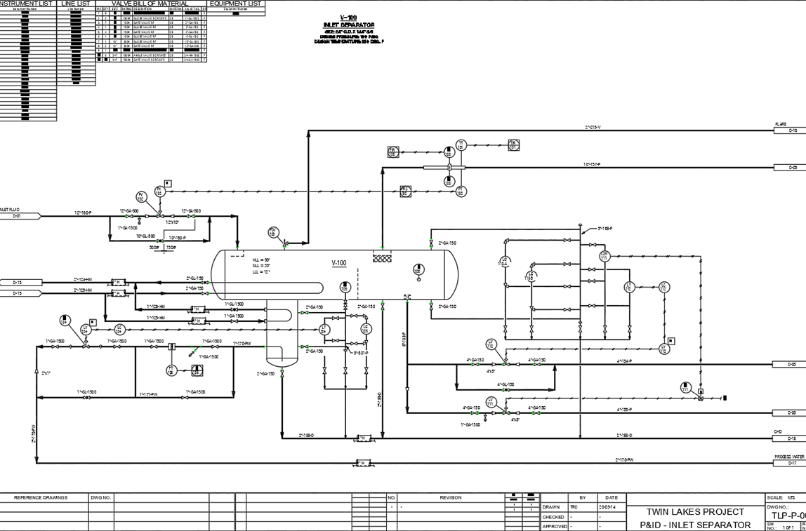
Piping and Instrumentation Diagrams (P&ID) are a significant component of a plant’s development, operation and ongoing plant modifications. P&ID drawings have a significant role during the plant’s design and lifecycle when plant maintenance and modification are needed. P&ID drawings demonstrate the physical sequence of flow and line interconnectivity among equipment all the way to the finished processed product. It shows systems connection, operational conditions such as pressure and temperature and identifies each line connecting these systems.
At the design stage, P&ID drawings provides the basis for the development of system control schemes to allow for further safety and operational investigations, such as HAZOP. In essence, P&ID drawings are the roadmap of the plant and must be maintained at all times.
For a demo of P&ID drawing development software, check out PROCAD’s PapriCAD P&ID or 2D DESIGNER AutoFLOW software.